
This week we are testing the serial output by the Arduino. This specific example has a nice graphical representation that visualizes the serial output that changes according to the potentiometer’s knob turning.
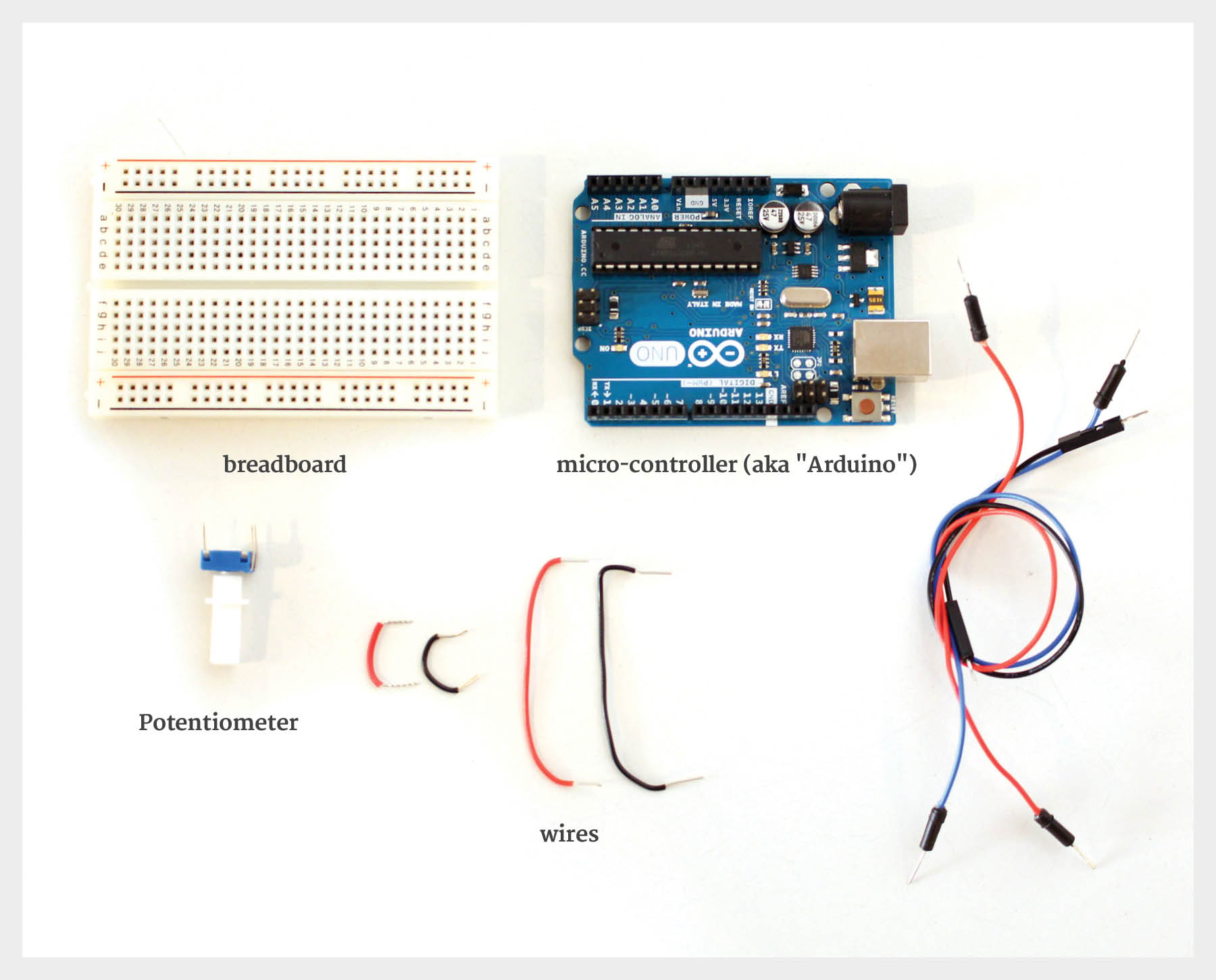
To start, we will need the following materials:
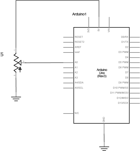
We will follow this schematic map in order to wire the components together:
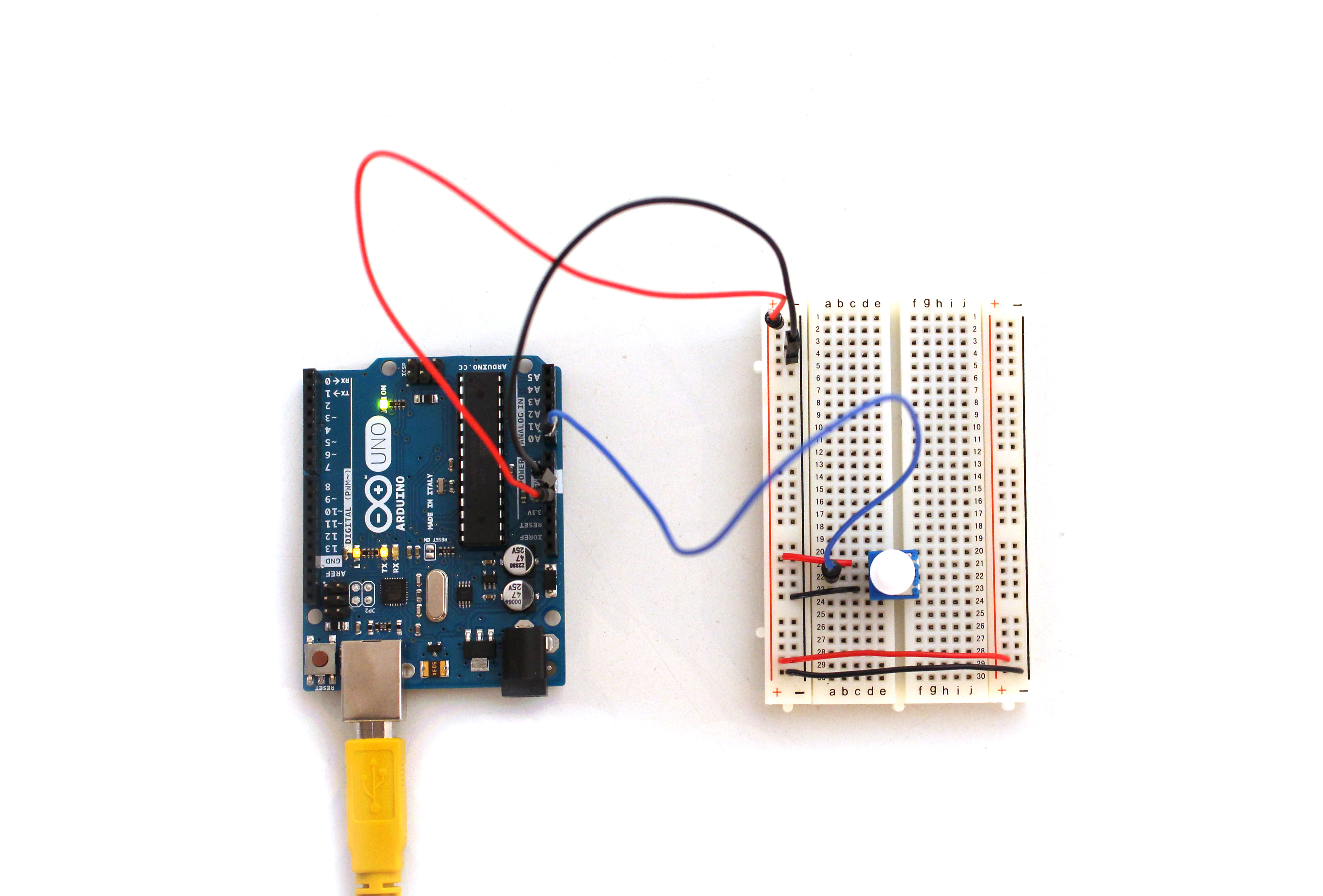
This is what the end result should look like:
Once everything is wired, use this code in Processing
import processing.serial.*;
float xPos = 0; // horizontal position of the graph

void setup () {
 Serial myPort;
 size(800, 600); // window size
 println(Serial.list()); // List all the available serial ports

String portName = "/dev/tty.usbmodem1421";
myPort = new Serial(this, portName, 9600);

background(#081640);
}

void draw () {
 // nothing happens in draw. It all happens in SerialEvent()
}

void serialEvent (Serial myPort) {
 // get the byte:
 int inByte = myPort.read();
 // print it:
 println(inByte);

float yPos = height - inByte;
// draw the line in a pretty color:
stroke(#A8D9A7);
line(xPos, height, xPos, height - inByte);

// at the edge of the screen, go back to the beginning:
 if (xPos >= width) {
 xPos = 0;
 // clear the screen by resetting the background:
 background(#081640);
 }
 else {
 // increment the horizontal position for the next reading:
 xPos = xPos + .5;
 }

}
Run the code and turn the potentiometer knob. You should see something similar to this!
1 Comment