
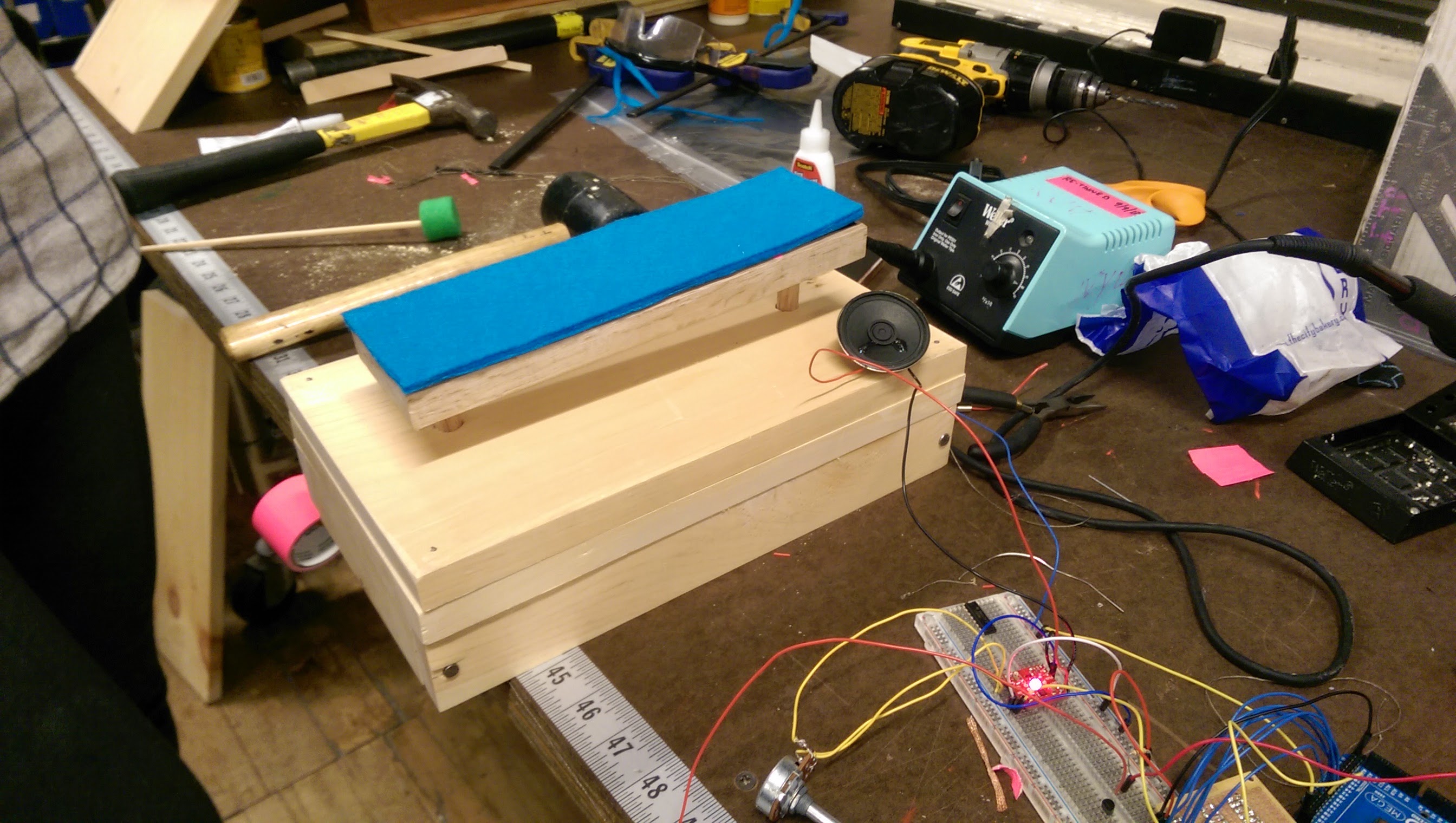
This week we setup our circuit, tested the sound and made sure our idea works.
Setup
How it Works
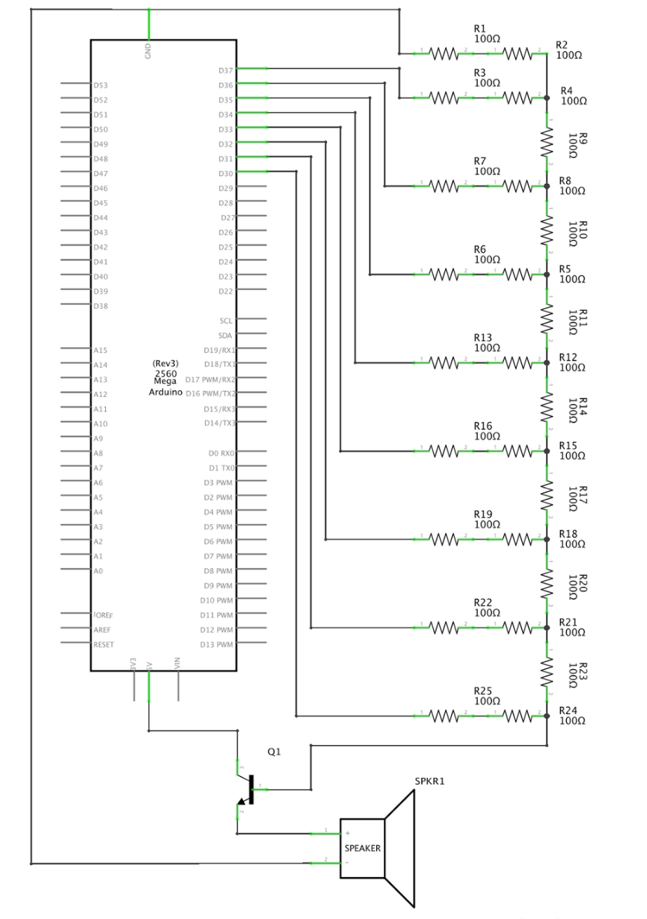
R2R Resistor Ladder
The resistor ladder is essentially a series of voltage divider so the input closest to the ground adds the least to the output (it’s the least significant bit), and the input closest to the output adds the most to the output (it’s the most significant bit).

Here is a video demonstrating each input individually, and then adding them all together.
Code
First we need to store the data that we want to output:
PROGMEM unsigned char data[48]
This stores a 48 byte array in the program memory – flash memory as opposed to SRAM. The Mega 2560 has 8kb of SRAM, and 256kb of flash memory. Our first test was a half second sound file sampled at 8kHz and was about 4kb. We want to have eight distinct notes, so we each one can be up to around 30kb meaning we can sample them at a much higher rate. Alternatively we can sample them at a lower rate and allow lots of different sounds. Next we set the pins as output:
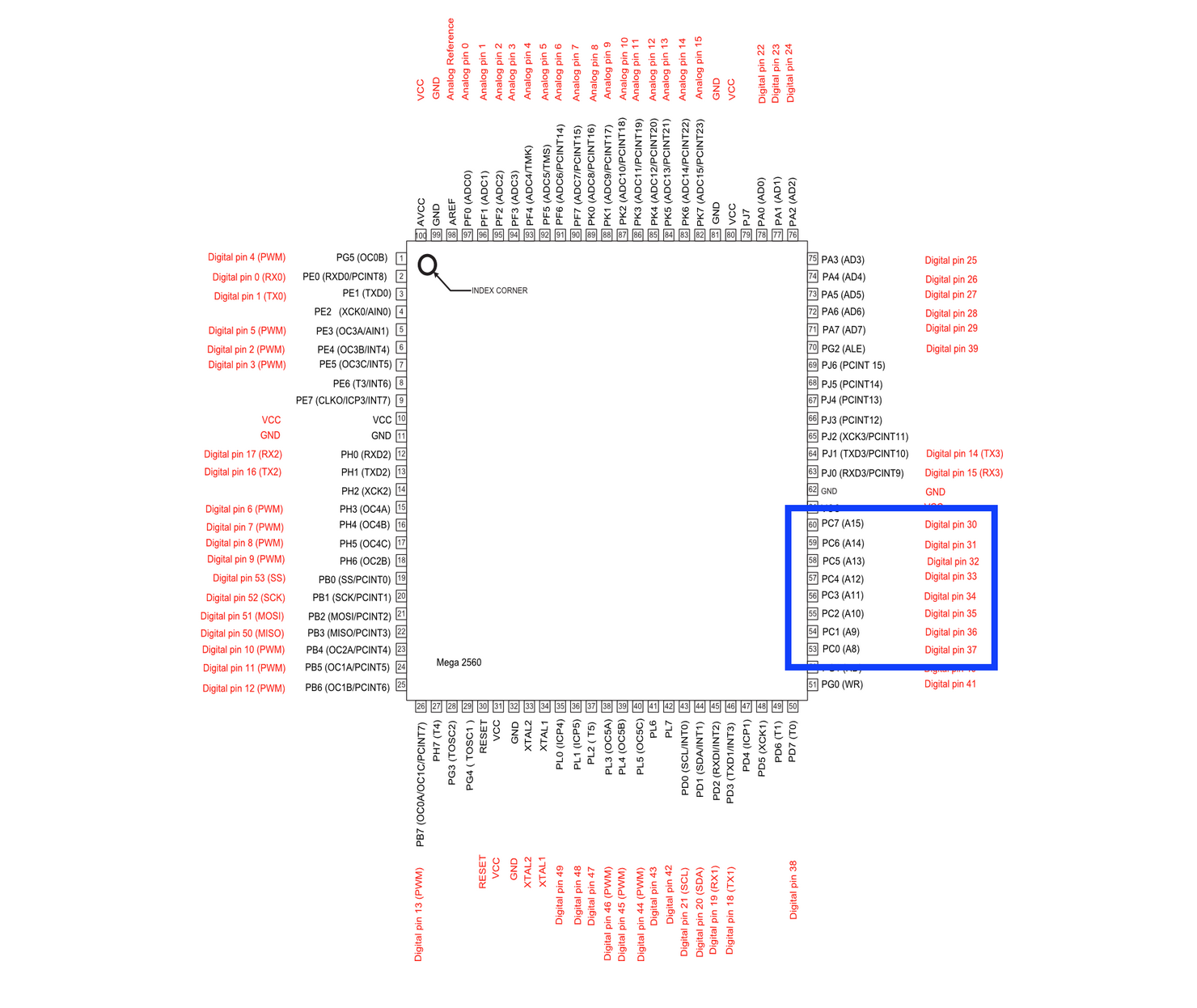
DDRC = 255;
DDRC is a register that controls whether Port C is input or output. Port C is the set of digital pins from 37 down to 30. By setting each bit in the DDRC register as a 1, each pin is set as output. 255 in binary is 11111111, so we could instead write:
DDRC = B11111111;
or
DDRC = 0xff
Next we actually change the output:
PORTC = pgm_read_byte(&(data[i++]));
PORTC controls the output of the pins 37 down to 30, similar to the way that DDRC controls whether those pins are input or output. Because the data array is stored in program memory instead of SRAM, we can’t just access it normally, so we need to use pgm_read_byte with a reference pointer in order to access it. We add one to ‘i’ after we set PORTC, so in the next time through the loop it outputs the next value in the data array. Because we sampled the audio at 8kHz, we need a delay in the loop. If the sample is at 8kHz, the period is 1/8000 seconds (125μs):
delayMicroseconds(125);
The Code Itself
#include <avr/pgmspace.h>

PROGMEM unsigned char data[48] = {0x00,0x01,0x02,0x03,0x04,0x05,0x06,0x07,0x08,0x09,0x0a,0x0b,0x0c,0x0d,0x0e,0x0f,0x10,0x11,0x12,0x13,0x14,0x15,0x16,0x17,0x18,0x19,0x1a,0x1b,0x1c,0x1d,0x1e,0x1f,0x20,0x21,0x22,0x23,0x24,0x25,0x26,0x27,0x28,0x29,0x2a,0x2b,0x2c,0x2d,0x2e,0x2f};

short i = 0;

void setup() {
DDRC = 255;
}

void loop() {

PORTC = pgm_read_byte(&(data[i++]));

if(i >= sizeof(data)) {
i = 0;
delay(1500);
}

delayMicroseconds(125);

}
The data in this code is just counting from 0 to 47. Real audio data uses thousands of bytes. We get the bytes by taking a sound in Audacity, saving it as a raw file 8-bit unsigned file, and converting the raw file to a header file using bin2h.
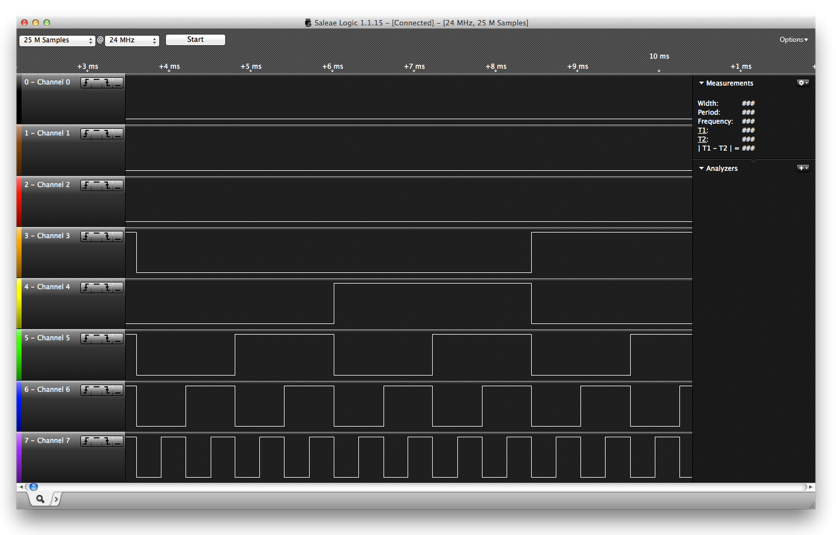
Output
Here is a screenshot of the logic coming out of the Arduino when we output the numbers 0 through 47:
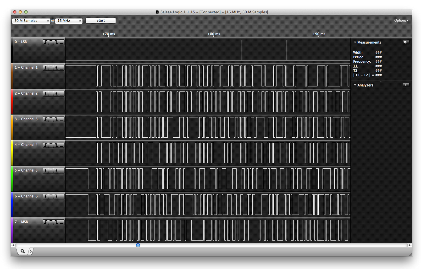
When we switch to the actual sound data, it looks like this:
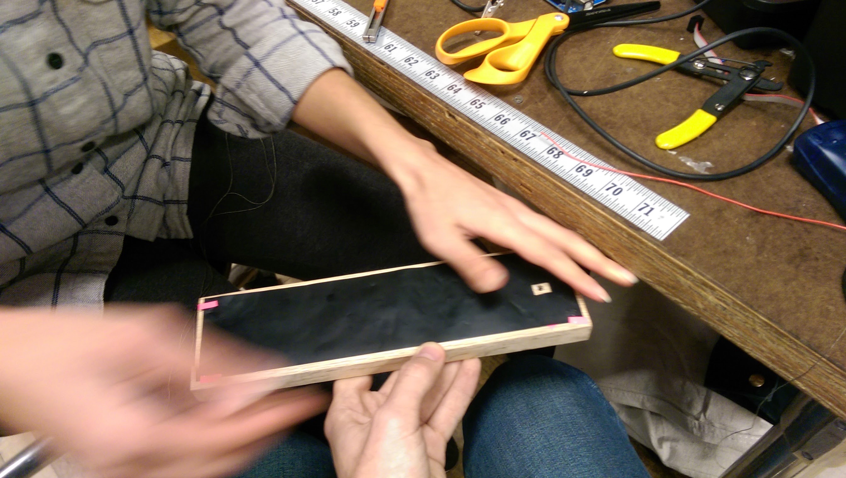
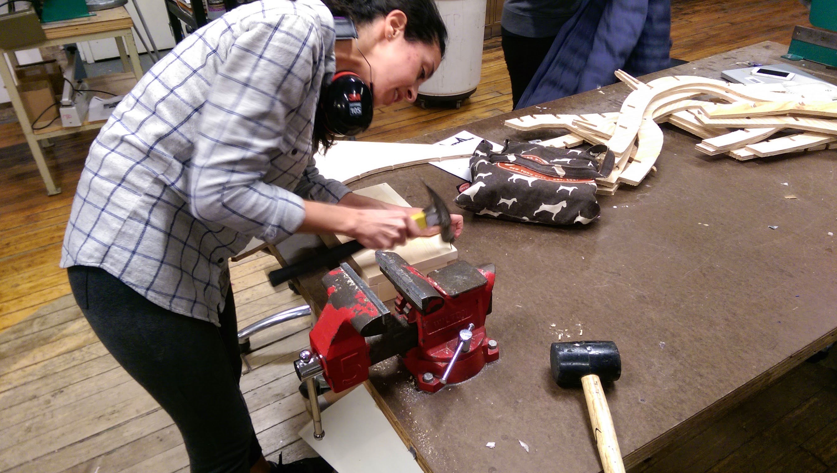
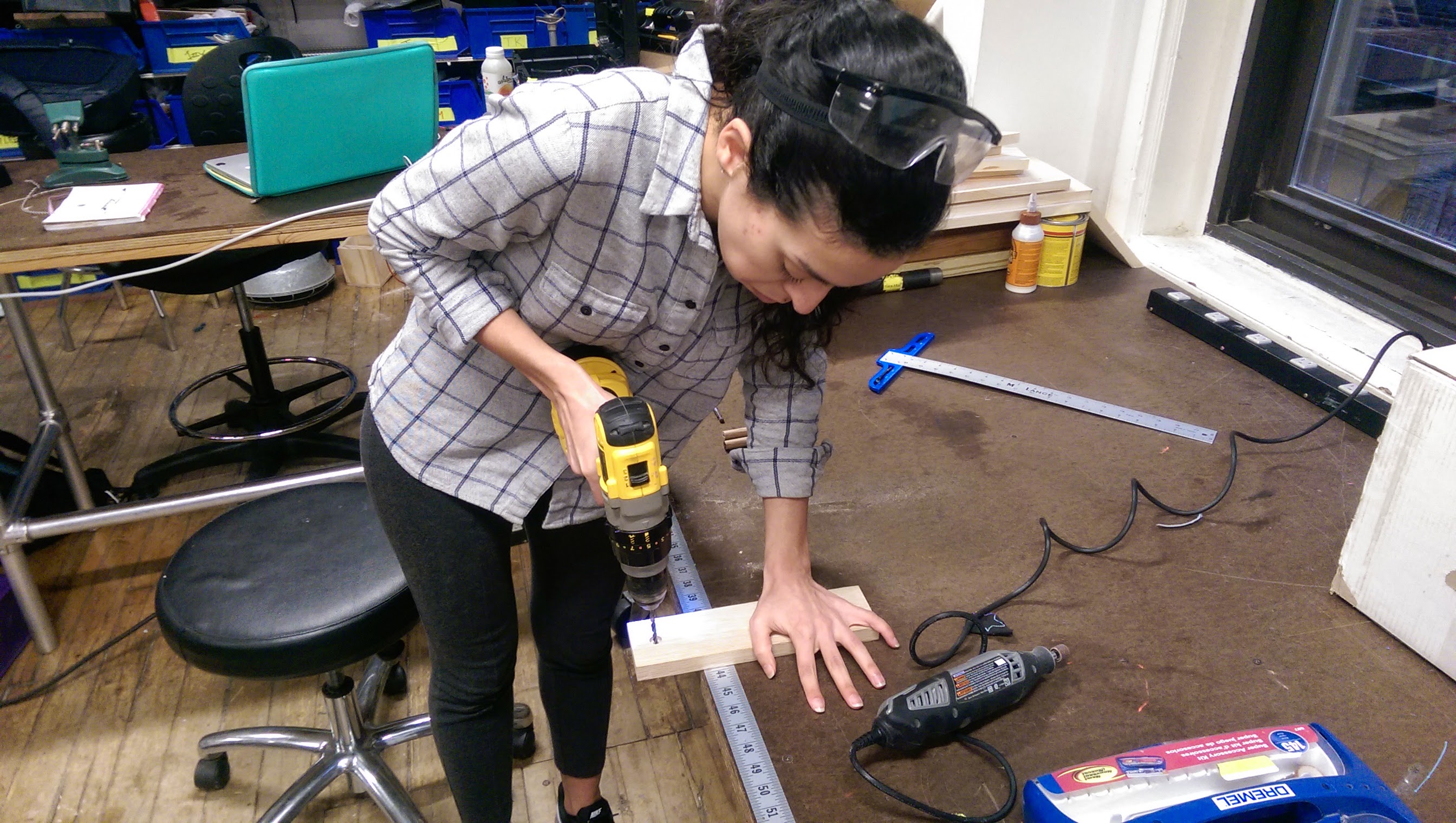
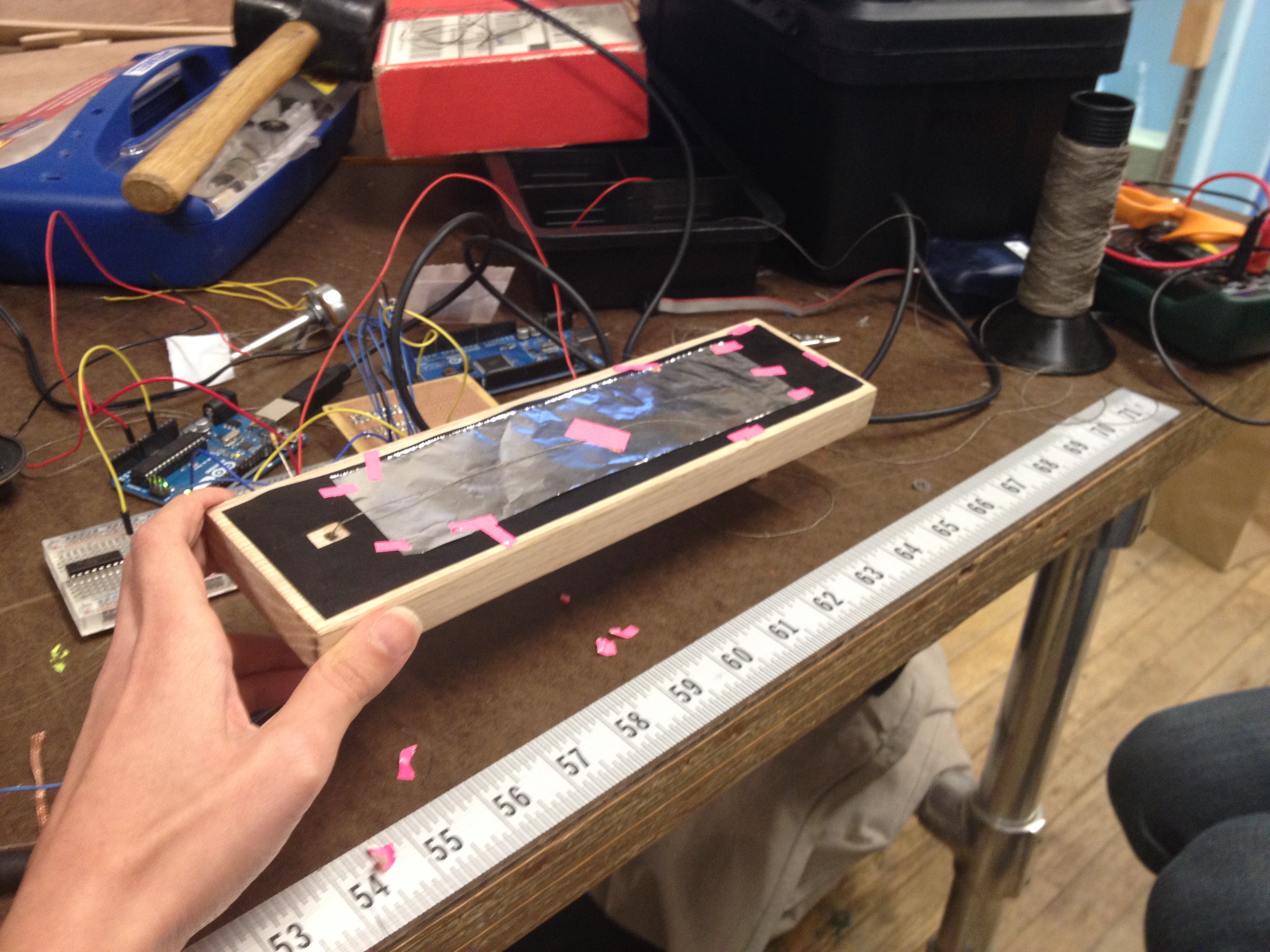
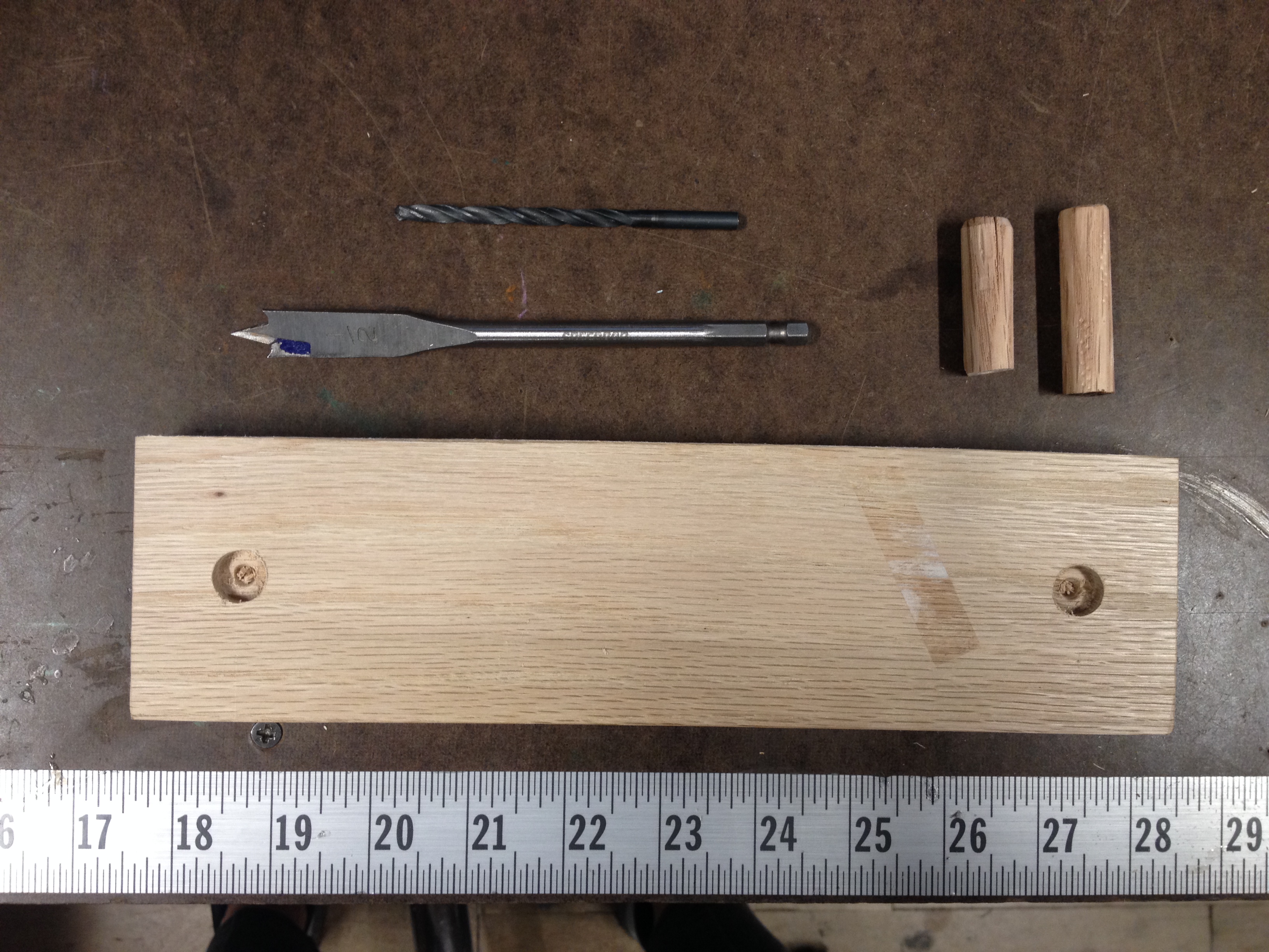
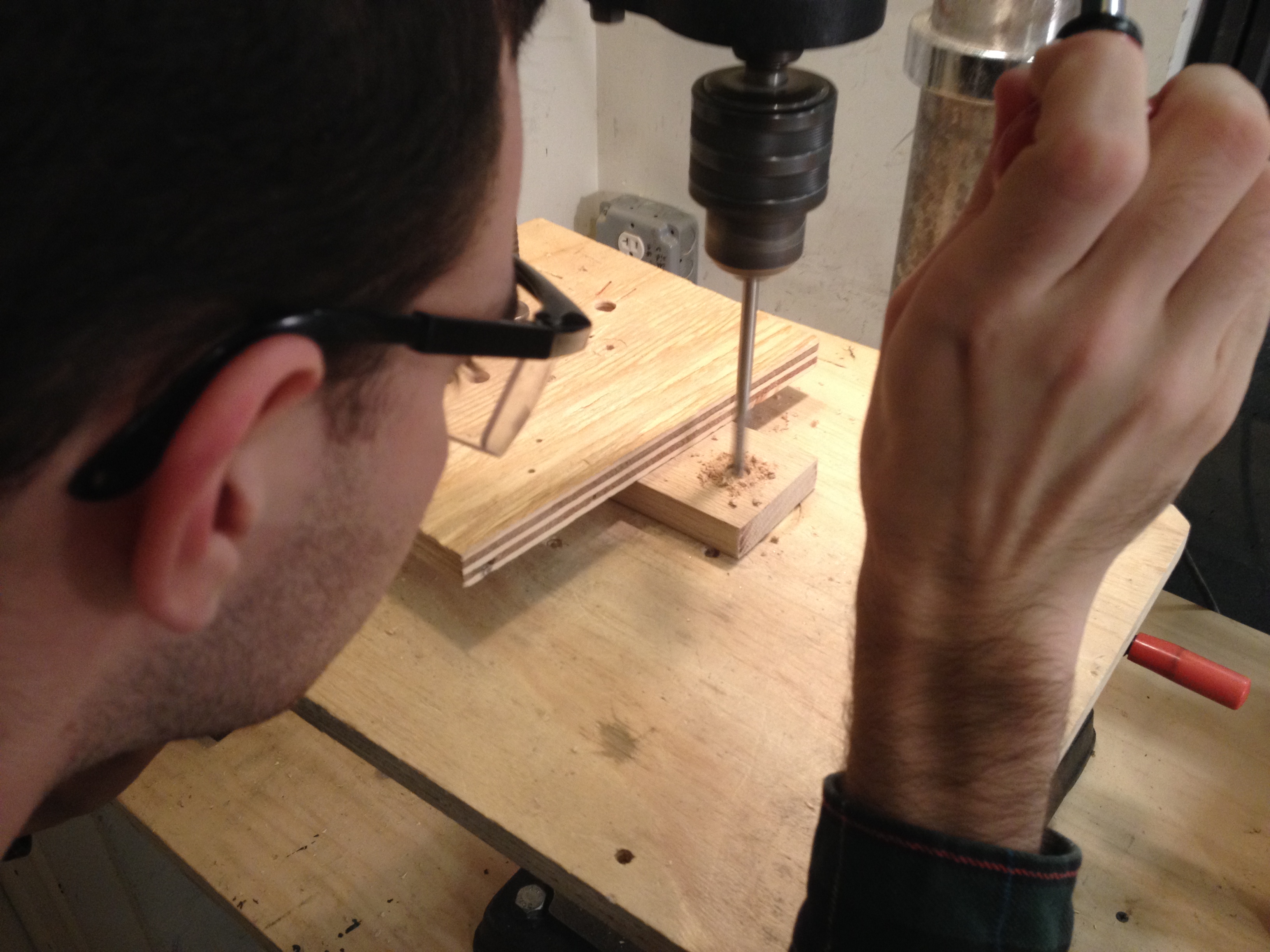
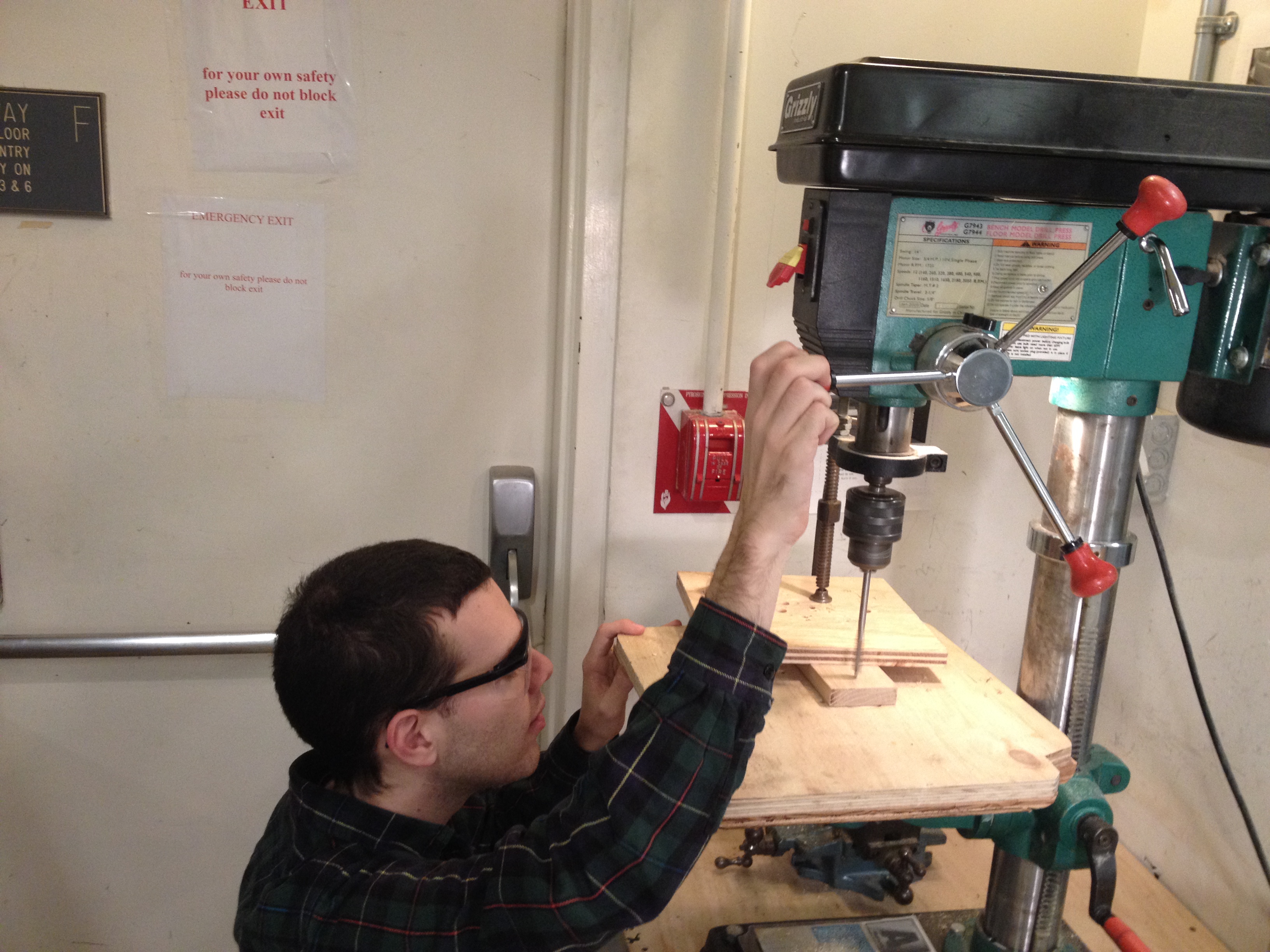
Assembling the prototype
Sources
https://www.youtube.com/watch?v=tUapZ_JdHLE
http://playground.arduino.cc/Learning/Memory
http://arduino.cc/en/Hacking/PinMapping2560
http://www.arduino.cc/en/Reference/PortManipulation
http://arduino.cc/en/Reference/PROGMEM
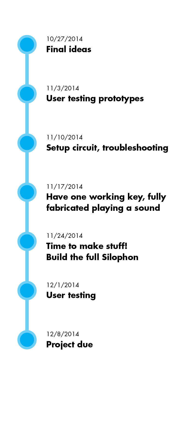
Timeline
1 Comment